
Test for insulation and sheath thickness of wire and cable products
author: Zhejiang Linquick Technology Co., Ltd.
2023-09-19
First, test equipment
A reading microscope or projector with a magnification of at least 10 times, with a reading of 0.01mm for both devices. If the insulation thickness is 0.5mm, read the third digit after the decimal point.
When in dispute, the reading microscope measurement is used as the baseline method.
A reading microscope or projector with a magnification of at least 10 times, with a reading of 0.01mm for both devices. If the insulation thickness is 0.5mm, read the third digit after the decimal point.
When in dispute, the reading microscope measurement is used as the baseline method.
Second, sample preparation
1. Preparation of insulation sample:
a) Remove all cladding from the insulation and pull out the conductor and isolation layer (if any). Be careful to avoid damaging the insulation. If the internal and external semi-conductive layer is attached to the insulation, it does not need to be removed.
b) Each specimen consists of an insulating sheet cut with an appropriate tool (sharp blade such as a razor blade, etc.) along a plane perpendicular to the conductor axis.
c) The core of flat flexible wires without sheaths should not be separated.
d) If there is an imprint mark dent on the insulation, it will thin the thickness there, so the specimen should take the section containing the mark.
1. Preparation of insulation sample:
a) Remove all cladding from the insulation and pull out the conductor and isolation layer (if any). Be careful to avoid damaging the insulation. If the internal and external semi-conductive layer is attached to the insulation, it does not need to be removed.
b) Each specimen consists of an insulating sheet cut with an appropriate tool (sharp blade such as a razor blade, etc.) along a plane perpendicular to the conductor axis.
c) The core of flat flexible wires without sheaths should not be separated.
d) If there is an imprint mark dent on the insulation, it will thin the thickness there, so the specimen should take the section containing the mark.
2. Sheath sample preparation:
a) Remove all elements (if any) inside and outside the sheath and cut a thin slice with an appropriate tool (sharp blade such as a razor blade, etc.) along the plane perpendicular to the cable axis.
b) If there is an imprint mark dent on the sheath, it will thin the thickness there, so the specimen should take the section containing the mark.
Note: For products that perform standards such as GB/T 5023, GB/T 5013, JB/T 8734, JB/T 8735, JB/T 10491, one section of cable sample should be taken from three places at least 1m apart.
The sample should be as thin and uniform as possible.
a) Remove all elements (if any) inside and outside the sheath and cut a thin slice with an appropriate tool (sharp blade such as a razor blade, etc.) along the plane perpendicular to the cable axis.
b) If there is an imprint mark dent on the sheath, it will thin the thickness there, so the specimen should take the section containing the mark.
Note: For products that perform standards such as GB/T 5023, GB/T 5013, JB/T 8734, JB/T 8735, JB/T 10491, one section of cable sample should be taken from three places at least 1m apart.
The sample should be as thin and uniform as possible.
Third, insulation thickness measurement test procedures
1. Sample pretreatment:
The sample should be stored at a temperature of (23±5)℃ for at least 3h before testing.
2. Test steps:
1. Sample pretreatment:
The sample should be stored at a temperature of (23±5)℃ for at least 3h before testing.
2. Test steps:
Place the specimen on the working surface of the device, and the cutting surface is perpendicular to the optical axis.
a) When the inside of the specimen is round, 6 points should be measured radially according to Figure 1. If the fan-shaped insulated wire core is used, measure 6 points according to the figure.
b) When insulation is cut from a stranded conductor, 6 points should be measured radially according to Figures 3 and 4;
a) When the inside of the specimen is round, 6 points should be measured radially according to Figure 1. If the fan-shaped insulated wire core is used, measure 6 points according to the figure.
b) When insulation is cut from a stranded conductor, 6 points should be measured radially according to Figures 3 and 4;
c) When the outer surface of the specimen is uneven, 6 points should be measured according to Figure 5;
d) When there are non-removable shielding layers inside and outside the insulation, the thickness of the shielding layer should be subtracted from the measured value. When there are non-removable shielding layers inside and outside the opaque insulation, it should be measured using a reading microscope;
e) Flat flexible wires without sheaths shall be measured according to Figure 6, and half of the shortest distance between the two conductors shall be taken as the insulation thickness of the insulated core. In any case, the first measurement should be made at the thinnest part of the insulation.
If the insulation specimen includes an imprint mark dent, the insulation thickness there should not be used to calculate the average thickness. However, in any case, the insulation thickness at the indentation of the impression mark shall comply with the minimum value specified in the relevant cable product standard.
If the specified insulation thickness is 0.5mm and above, the reading should be measured to two decimal places (in mm); If the specified insulation thickness is less than 0.5mm, the reading should be measured to three decimal places, the third place is an estimate.
d) When there are non-removable shielding layers inside and outside the insulation, the thickness of the shielding layer should be subtracted from the measured value. When there are non-removable shielding layers inside and outside the opaque insulation, it should be measured using a reading microscope;
e) Flat flexible wires without sheaths shall be measured according to Figure 6, and half of the shortest distance between the two conductors shall be taken as the insulation thickness of the insulated core. In any case, the first measurement should be made at the thinnest part of the insulation.
If the insulation specimen includes an imprint mark dent, the insulation thickness there should not be used to calculate the average thickness. However, in any case, the insulation thickness at the indentation of the impression mark shall comply with the minimum value specified in the relevant cable product standard.
If the specified insulation thickness is 0.5mm and above, the reading should be measured to two decimal places (in mm); If the specified insulation thickness is less than 0.5mm, the reading should be measured to three decimal places, the third place is an estimate.
Fourth, sheath thickness measurement test procedures
1. Sheath sample pretreatment:
The sample should be stored at a temperature of (23±5)℃ for at least 3h before testing.
2. Sheath test steps:
Place the specimen on the working surface of the measuring device, and the cutting surface is perpendicular to the optical axis.
a) When the inside of the specimen is round, 6 points should be measured radial according to Figure 1;
b) If the inner circular surface of the specimen is substantially irregular or not smooth, 6 points should be measured radially at the thinnest of the sheath as shown in Figure 7;
1. Sheath sample pretreatment:
The sample should be stored at a temperature of (23±5)℃ for at least 3h before testing.
2. Sheath test steps:
Place the specimen on the working surface of the measuring device, and the cutting surface is perpendicular to the optical axis.
a) When the inside of the specimen is round, 6 points should be measured radial according to Figure 1;
b) If the inner circular surface of the specimen is substantially irregular or not smooth, 6 points should be measured radially at the thinnest of the sheath as shown in Figure 7;
c) When there is a conductor inside the specimen causing deep grooves, it should be measured radially at the bottom of each groove according to Figure 8. When the number of grooves exceeds 6, it should be measured according to item b);
d) When the outer surface of the sheath is irregular due to scraping tape or rib sheath shape, it should be measured according to Figure 9;
e) For sheathed flat flexible wires, measurements shall be made in the direction roughly parallel to the short axis and on the long axis of each insulated wire core section as shown in Figure 10. But at any rate you should measure a little at the thinnest point;
d) When the outer surface of the sheath is irregular due to scraping tape or rib sheath shape, it should be measured according to Figure 9;
e) For sheathed flat flexible wires, measurements shall be made in the direction roughly parallel to the short axis and on the long axis of each insulated wire core section as shown in Figure 10. But at any rate you should measure a little at the thinnest point;
f) Flat sheathed cables with six cores and below shall be measured according to Figure 11:
- Measure at both ends of the arc along the long axis of the cross section.
- Measure on the first and last insulated core on the flat sides; If the thinnest thickness is not included in the above measurements, the measurement of the thickness at the thinnest point and in the direction opposite to it should be increased.
The above provisions are also applicable to the measurement of the sheath thickness of flat cables with more than six cores, but the middle insulating core should be increased or one of the middle two insulating cores should be taken for measurement when the insulating core is an even number.
In any case, a measurement should be made at the thinnest point of the sheath.
If the jacket sample includes an indentation, the thickness there should not be used to calculate the average thickness. However, in any case, the thickness of the sheath at the indentation of the embossed mark shall comply with the minimum value specified in the relevant cable product standard.
- Measure at both ends of the arc along the long axis of the cross section.
- Measure on the first and last insulated core on the flat sides; If the thinnest thickness is not included in the above measurements, the measurement of the thickness at the thinnest point and in the direction opposite to it should be increased.
The above provisions are also applicable to the measurement of the sheath thickness of flat cables with more than six cores, but the middle insulating core should be increased or one of the middle two insulating cores should be taken for measurement when the insulating core is an even number.
In any case, a measurement should be made at the thinnest point of the sheath.
If the jacket sample includes an indentation, the thickness there should not be used to calculate the average thickness. However, in any case, the thickness of the sheath at the indentation of the embossed mark shall comply with the minimum value specified in the relevant cable product standard.
Fiveth. Data processing
The average value of the measured insulation or sheath thickness, revised as the average value of the insulation or sheath thickness; The minimum value of all measured data, as the minimum thickness value of insulation or sheath.
Sixth. Test records
(1) Sample number, sample specification and model;
(2) Test date, pretreatment environment temperature and test environment temperature;
(3) each thickness measurement of the sample;
(4) Average and minimum results.
(2) Test date, pretreatment environment temperature and test environment temperature;
(3) each thickness measurement of the sample;
(4) Average and minimum results.
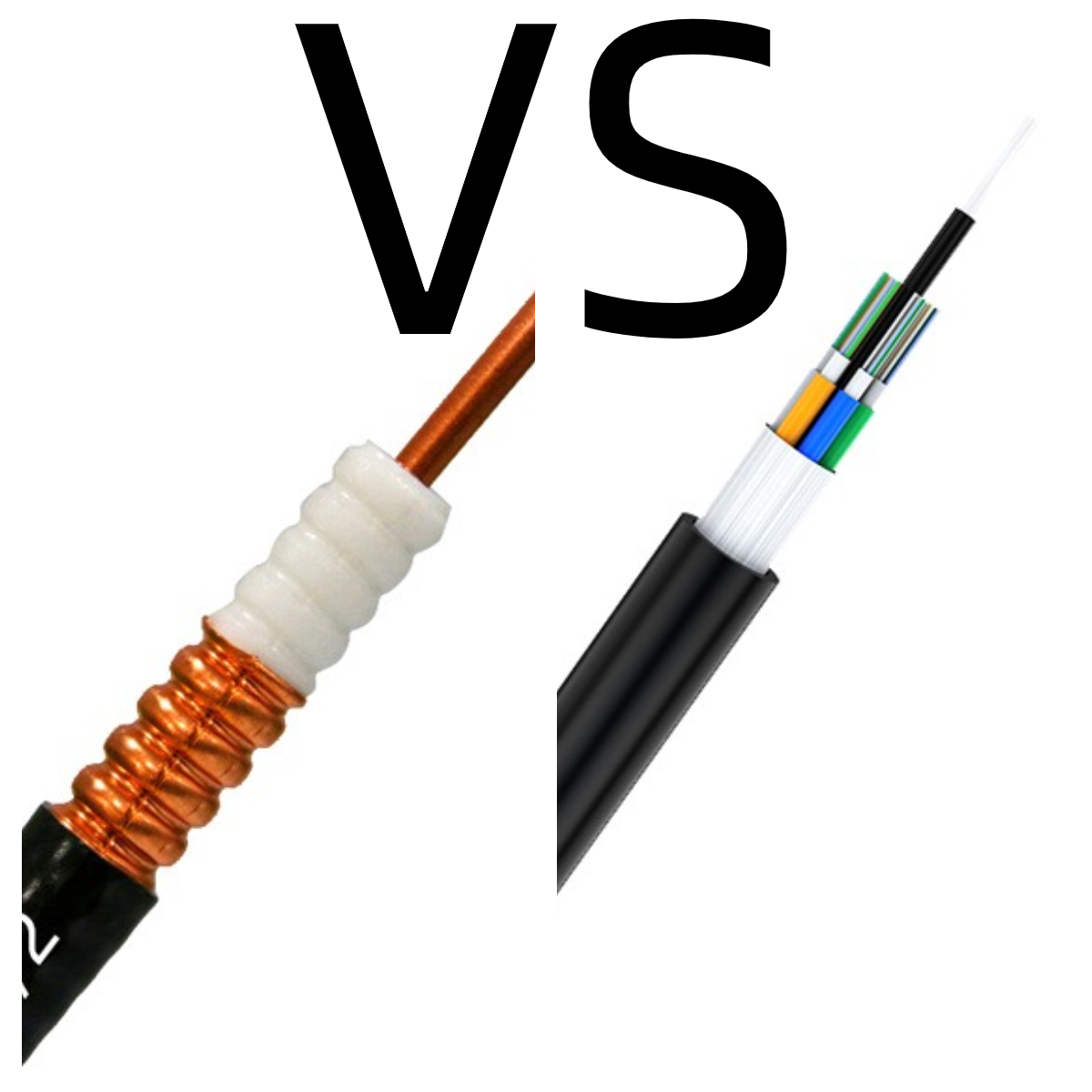 Analysis of advantages of Copper cables and Optic fiber
 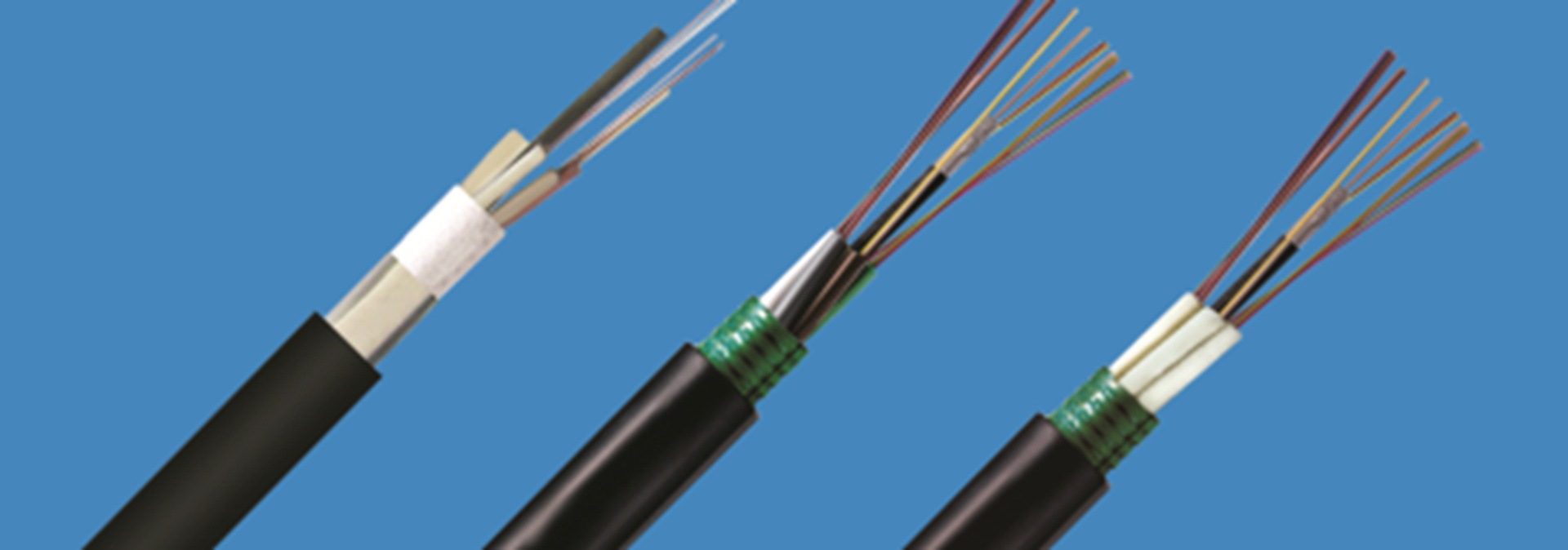 Structure and type of optical cable
 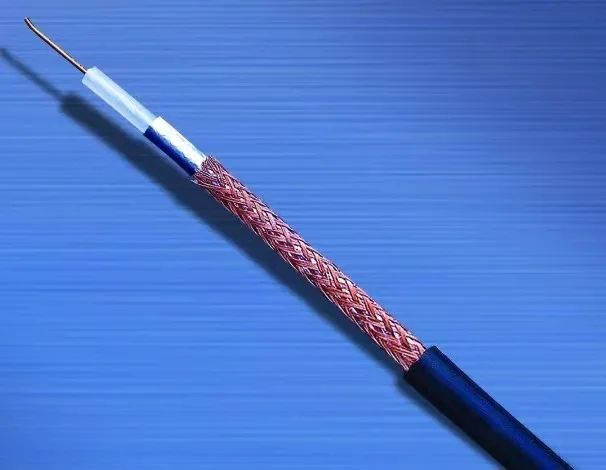 Discussion on measurement method of characteristic impedance of RF coaxial cable
 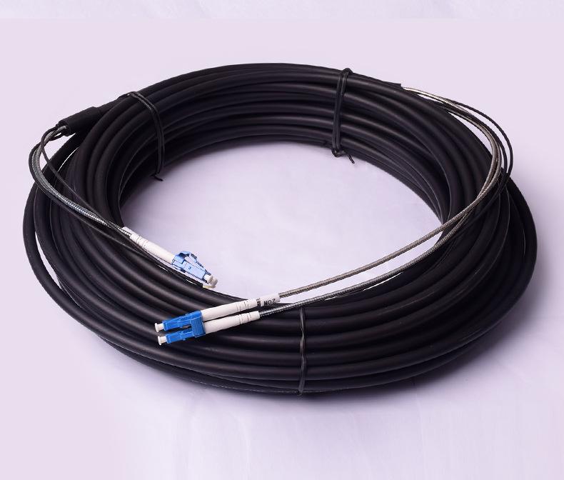 What is a fiber optical feeder cable
  Zhejiang Linquick Technology will participate in the 134th Canton Fair
  Introduction to RF coaxial cable
  Five common cable classification
  What is FTTA Remote Cable
  Congratulations to Zhejiang Linquick 24th CIOE a complete success
  Structure and type of optical cable
  Outdoor optical cables: the link that connects the world
  Analysis and improvement of drop cable fiber attenuation problem
  Wire and cable quality test three important indicators
  Laying method of communication optical cable
  Teach you to identify and choose coaxial cable and twisted pair
  Overview of material and structure of waterproof cable
  Process requirements and instructions for armored cables
  A brief discussion on the application of cluster wire
  Safety requirements and storage methods for wire and cable use
  Zhejiang Linquick NETCOM2023 exhibition was successfully held