
Discussion on measurement method of characteristic impedance of RF coaxial cable
author: Zhejiang Linquick Technology Co., Ltd.
2023-10-24
As a transmission line, RF coaxial cable is widely used in communication systems. The characteristic impedance is the first electrical parameter to be considered in the design and selection of RF coaxial cable. The maximum power transmission and minimum signal reflection all depend on the characteristic impedance of the cable and its matching with other components in the system. In practical applications, the working state of the transmission line can be easily analyzed according to the characteristic impedance of the cable, so it is very important to measure its value accurately.
First, the Definition of characteristic impedance.
When the electromagnetic wave propagates on the cable, there are usually incident waves propagating forward and reflected waves propagating back, and the incident waves and reflected waves superimposed on each other to form standing waves. The ratio of total voltage to total current at any point in a transmission line is defined as the input impedance at that point looking towards the load. In general, the input impedance of a transmission line is not only related to the length of the line but also to the frequency, however when the transmission line is infinitely long, there are only forward waves on the transmission line (traveling waves). At this time, the input impedance at any point of the transmission line is independent of the line length but is equal to a constant value of Zc, which is called the characteristic impedance of the transmission line.
In addition, when the transmission line terminates with a constant value of pure resistance load, the input impedance at any point of the transmission line is equal everywhere and independent of the line length. This constant resistance value is the characteristic impedance value of the transmission line. The characteristic impedance Zc of the RF coaxial cable depends only on the diameter of the inner and outer conductors of the transmission line and the equivalent dielectric constant of the filling medium between them and has nothing to do with the line length.
When the electromagnetic wave propagates on the cable, there are usually incident waves propagating forward and reflected waves propagating back, and the incident waves and reflected waves superimposed on each other to form standing waves. The ratio of total voltage to total current at any point in a transmission line is defined as the input impedance at that point looking towards the load. In general, the input impedance of a transmission line is not only related to the length of the line but also to the frequency, however when the transmission line is infinitely long, there are only forward waves on the transmission line (traveling waves). At this time, the input impedance at any point of the transmission line is independent of the line length but is equal to a constant value of Zc, which is called the characteristic impedance of the transmission line.
In addition, when the transmission line terminates with a constant value of pure resistance load, the input impedance at any point of the transmission line is equal everywhere and independent of the line length. This constant resistance value is the characteristic impedance value of the transmission line. The characteristic impedance Zc of the RF coaxial cable depends only on the diameter of the inner and outer conductors of the transmission line and the equivalent dielectric constant of the filling medium between them and has nothing to do with the line length.
Second, the measurement method of characteristic impedance.
The characteristic impedance of RF coaxial cable can be measured by the frequency domain method or time domain method. The frequency domain method generally uses a vector network analyzer to test the cable performance. Because the vector network analyzer uses a bandpass filter and digital filter, it has very low background noise, so it can accurately measure the cable characteristic impedance. According to the different transmission directions of the test signal, the frequency domain method can be divided into transmission measurement and reflection measurement. Among the commonly used RF coaxial cable characteristic impedance measurement methods, transmission phase method, transmission phase difference method, open or short circuit resonance method belongs to the transmission measurement in the frequency domain method, and the newer single connector measurement method belongs to the reflection measurement in the frequency domain method.
The voltage standing wave ratio of the RF connector is mainly caused by the inhomogeneity of the connector's internal impedance and the deviation from the characteristic impedance of the cable. Because the characteristic impedance of the RF connector is relatively easy to control (such as (50±0.5) Ψ), the internal impedance inhomogeneity includes the small standing wave ratio caused by the discontinuous capacitance caused by the size mutation, and in the low frequency (such as 200MHz) segment below, the standing wave ratio of the connector is generally only about 1.005, far less than the voltage standing wave ratio of the cable assembly. Therefore, the voltage standing wave ratio of the connector can be ignored, but the reflection caused by the impedance inhomogeneity of the measured cable can not be ignored, and this part of the influence should be eliminated during the test, so that the most important reflection source in the single connector comes from the deviation between the cable impedance and the standard impedance, and finally the characteristic impedance of the measured cable can be directly obtained by measuring the voltage standing wave ratio of the single connector.
In the RF segment, the characteristic impedance of the RF cable is independent of the frequency, so it only needs to be measured by the transmission phase method at any frequency within the 30 ~ 200MHz frequency range specified in the GB 4098.3 "RF Cable Characteristic Impedance Measurement Method". Because of the large error of the transmission phase difference method, it is best to use it with caution. The single connector method is simple to operate, accurate to measure the data, and directly linked to the voltage standing wave ratio, with strong practicability, is a convenient and practical method to measure the characteristic impedance of RF cable, it is recommended to use.
In the RF segment, the characteristic impedance of the RF cable is independent of the frequency, so it only needs to be measured by the transmission phase method at any frequency within the 30 ~ 200MHz frequency range specified in the GB 4098.3 "RF Cable Characteristic Impedance Measurement Method". Because of the large error of the transmission phase difference method, it is best to use it with caution. The single connector method is simple to operate, accurate to measure the data, and directly linked to the voltage standing wave ratio, with strong practicability, is a convenient and practical method to measure the characteristic impedance of RF cable, it is recommended to use.
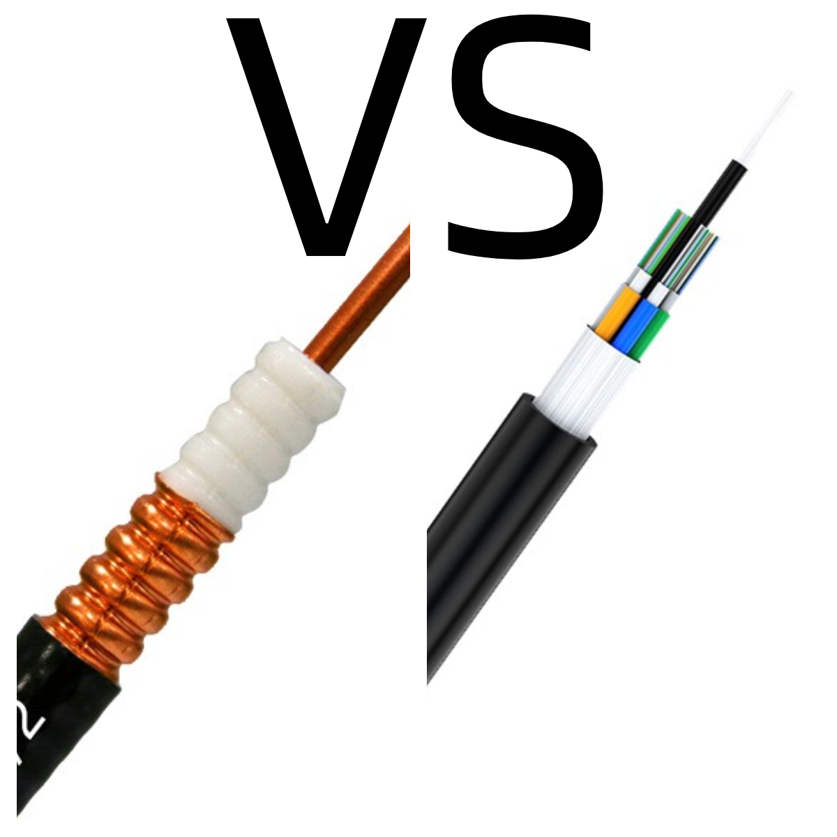 Analysis of advantages of Copper cables and Optic fiber
 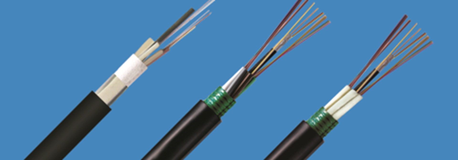 Structure and type of optical cable
 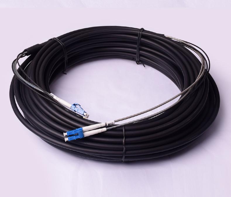 What is a fiber optical feeder cable
 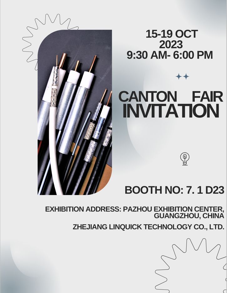 Zhejiang Linquick Technology will participate in the 134th Canton Fair
  Introduction to RF coaxial cable
  Five common cable classification
  What is FTTA Remote Cable
  Test for insulation and sheath thickness of wire and cable products
  Congratulations to Zhejiang Linquick 24th CIOE a complete success
  Structure and type of optical cable
  Outdoor optical cables: the link that connects the world
  Analysis and improvement of drop cable fiber attenuation problem
  Wire and cable quality test three important indicators
  Laying method of communication optical cable
  Teach you to identify and choose coaxial cable and twisted pair
  Overview of material and structure of waterproof cable
  Process requirements and instructions for armored cables
  A brief discussion on the application of cluster wire
  Safety requirements and storage methods for wire and cable use
  Zhejiang Linquick NETCOM2023 exhibition was successfully held